BACK TO HOME PAGE

The James Millen Society

Dennis Petrich, KØEOO

About a year or so ago I thought I would try and use the two Millen modules I had acquired many years ago with the 90881 500-watt RF deck and build a medium power James Millen Transmitter.

Well with a little bit of eBay surfing I was able to find the 90881 RF deck, a pristine 90800 RF exciter with 80m to 10m worth of plug-in coils and the rather rare 90831 speech amplifier/modulator from Dale Braun WD9GWH. I already had collected the 90905 5” scope and 90700 Vari-arm VFO while I lived in California.

Next, I found the documentation with the earlier James Millen modules to be a bit lacking in completeness. It took a while to figure out just how to use the exciter for example and even though the documentation for the RF deck was better, they didn’t address plate modulation or how to change the link for the different bands. The best information I found was on the “James Millen Society” web site. There I found valuable information on Millen module variations, how to get schematics and a very nice write-up by Don Buska, N9OO. His write-up is on putting a complete 50-watt AM/CW Millen transmitter on the air. See the Millen web site for details, http://www.isquare.com/millen/index.htm

The modules I collected for my Millen station are:

  • 90881 500W RF deck w/812A’s in class C
  • 90905 5” rack mount monitor scope
  • 90800 160m-10m, 50w 807 exciter to drive RF deck
  • 90831 40w speech amp to drive Taylor TZ-40’s or 811A’s in class B
  • 90700 Vari-arm VFO

Once I had the modules I needed, I started developing a list of features, or capabilities I thought would be nice in the finished product. My design objectives were:

  • A tabletop transmitter vs. floor standing transmitter.
  • CW and Phone operation from 160m to 10m.
  • Because the rig would use link-coupled coils, I wanted to use a rack cabinet with open back and sides for easy access.
  • Each of the Millen modules to be easily removable from the rack by having their electrical connections on separate multi-pin plugs.
  • The 1500v supply and modulator to set on the floor on wheels.
  • I wanted to be able to run the tabletop transmitter with or without the HV/modulator chassis connected.
  • Shunt choke plate modulation to remove DC current flow from the modulation transformers secondary.
  • “Negative cycle loading” to protect the mod iron.
  • High, low, bias and filament voltages for the exciter, speech amp, scope and VFO are all part of the tabletop transmitter power supply chassis.
  • “Tune/Operate” switching from the front panel to reduce the PA’s high voltage in tune.
  • “CW/Phone” switch on the 90831-speech amp to control the CW & Phone operation for the entire transmitter.
  • Push-to-talk (PTT) added to the 90831 to control the rig on phone and have a “plate” switch to use for CW.
  • Add an exciter grid current meter to the front panel.
  • Add power modulator plate current meter to the front panel.
  • Add relay contacts to control an external antenna relay and receiver muting.
  • Setup 5” scope to display either an RF envelope pattern or trapezoid pattern.

You can see from the photo's (below), schematics and the cable pin-out list how I interconnected each of the Millen modules with each other and through the power supplies. The schematic diagram indicate the cable plug number and pin on the plug, P2/7, is plug #2 pin #7. If you think you see any mistakes or have any questions please let me know via email, I’m sure I missed something….

Once all of the wiring issues were resolved, I was on the air with 250 watts of clean RF and great audio reports. In fact, the modulator is capable of over modulating the 812A’s quite easily. So I tend to watch the trapezoid as I talk making sure I don’t push it too hard. Remember I added K6AD’s negative cycle loading circuit. Well I added it after I noticed how easy it was to over modulate the 812A’s. Even though the NCL circuit isn’t designed to do more than protect the mod iron I find it keeps me from over modulating when that periodic loud sound hits. Reports on the air indicate smooth crisp audio with no hints of distortion; looks like Millen did a good job, a testimony to the quality built into each module.

Well I have to say, being one of the first on the air with the James Millen 500w RF deck, plate modulated, is turning out to be more fun than I anticipated. Many of the “good fellows” belonging to the James Millen Society are now very interested in getting their Millen transmitters operational and on the air…. Now the next thing we need is a James Millen net on 75 meters to flush out more of those fine rigs….

I hope this article will help others put their Millen rigs on the air. I am including the schematics, cable pin lists, pictures and a short write-up on the project so other James Millen aficionados can get an idea for their own project. If you have any questions please do not hesitate to email me. 73, Dennis.

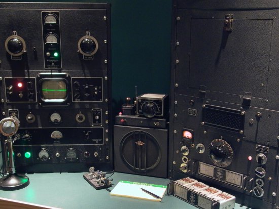
FIGURE 1 - This shows the completed James Millen 500w transmitter in my shack connected up with a 1946 vintage HRO-5RA1. The 90700 Vari-arm VFO is setting on top of the HRO-5 speaker. In the photo, you can see the two meters and the green and red lights on the bottom panel of the transmitter; that is the front panel of the power supply for the tabletop portion of the transmitter. The Millen modules, from top to bottom are the 90881-500w RF deck with 812A tubes running class C. The 90905 5" scope to monitor the RF envelop or trapezoid pattern. The 90800-50w exciter with 6L6 and 807 and the 90831-speech amp with 6146's in its output driving the grids of the 811A's in class B in the power modulator.

FIGURE 2 - The high voltage power supply and the power modulator. View schematics of the power supply and modulator here! The choke to the right is in series with the HV to the RF deck. The modulation iron is in the back at the left on the other side of the 811A tubes. The mod iron is capacitively coupled across the choke to take the DC off the mod iron secondary; a trick used in many broadcast transmitters. You can see the interconnect cables at the right of the chassis and the two chokes and the HV transformer on the right side of the chassis. The three relays near the center are for Tune/operate, CW/Phone and Plate ON/OFF control.

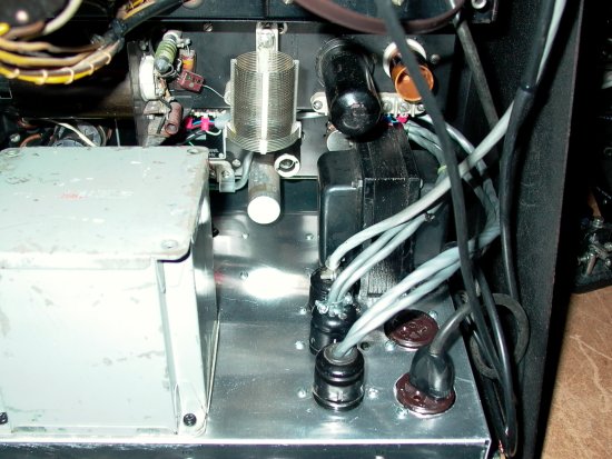
FIGURE 3 - The bottom side of the HV supply and power modulator. I chose to connect two smaller chassis vs. one larger chassis due to the weight of all the transformers. The trick worked pretty well but I think a steel chassis would have been even sturdier. The power supply filters are on the right and the coupling cap for the modulation is at the top with one of the CW/Phone relays at top left. The small circuit board between the relay and the capacitor is the negative cycle loading circuit. In the lower right of the chassis is the plate relay and at the top right is the filament transformer for the 811A's or the TZ-40's. At this time, I'm using 811A's because with 1450 volts the zero signal plate current is about 60ma. The zero signal plate current with the TZ-40's is higher so I would need to add about -9 volts of bias to run those tubes correctly.

FIGURE 4 - Top view of the high voltage power supply and power modulator. To the left of the 811A's is the mod iron and to the right of the tubes is the 25H modulation choke. The plate transformer is center back, the swinging choke is back left, and the smoothing choke is back right.

FIGURE 5 - Back of the transmitter. The bottom chassis is the homebrew supplies for the exciter, speech amp, VFO, and AC power for the RF decks filament supply. The bias supplies are located on this chassis.

FIGURE 6 - Notice the multi-pin plugs; each one is for a different Millen module. This way I can easily remove one of the modules for repair. The two-120v outlets in the foreground are switched from the filament ON/OFF switch. One is for the 90905 scope and the other has an isolation transformer for the 90700 VFO. The 90700 VFO is an AC/DC design that doesn't like being connected to a circuit with a ground fault detector.

FIGURE 7 - Bottom view of the low voltage supplies for the modules in the tabletop transmitter. This supply includes the 500v for the exciter and speech amp. The 240v for the speech amp and the three -45v bias supplies for the RF deck, speech amp and the exciter. The filament supply for the speech amp and exciter is on this chassis as is all of the switching circuits for the entire transmitter; plate switch, filament switch, tune/operate switch, exciter grid current meter and modulation cathode current meter. The CW/Phone switch is located on the 90831-speech amp and controls two relays on the HV supply to switch the transmitter from Phone to CW. Look at the schematics for details.

BACK TO HOME PAGE - TOP OF PAGE